Series A-135-4 contains several modules which are used to built a voltage controlled performance mixer. The modules of the A-135-4 series can be combined with the (non voltage controlled) mixer modules A-138o/p.
A-135-4 modules in detail:
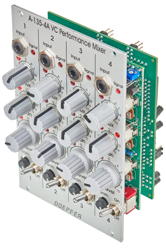
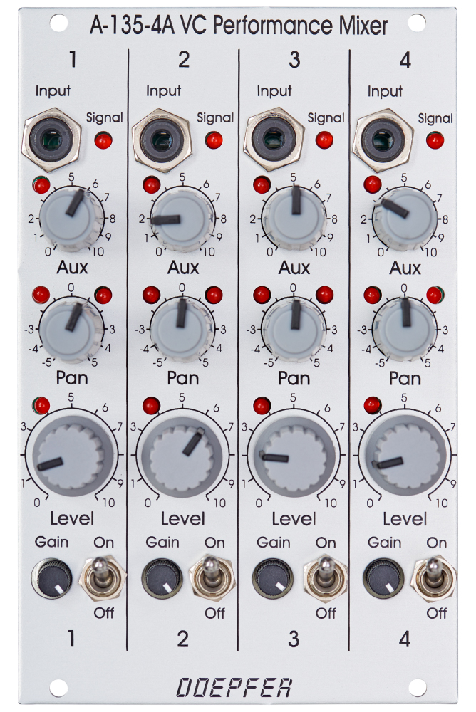
A-135-4A
A-135-4A is the main module. It is very similar to module A-138p, but with voltage control for all parameters (except gain). Also the front panels of A-135-4A and A-138p are very similar. The only difference are the additional LEDs which are used to display the magnitudes of all voltage controlled parameters. This is necessary because the positions of the manual controls do not necessarily correspond to the resulting parameter value because these are composed by both the manual controls and the applied external control voltages (via A-135-4B). Without LEDs one would be left in the dark in regard to the actual parameter value.
A-135-4A contains four high quality voltage controlled amplifers (VCA) for each channel: one for the main level, two for panorama left/right and one for aux. The control scales for all parameters are linear. Altogether 16 VCAs are included in the module. High end linear VCAs manufactured by Curtis/USA are used (CEM3381). The 16 LEDs display roughly the amplification of the VCA in question.
Module A-138o is used as output module for the A-135-4A. A-135-4A and A-138p can be connected together to the same A-138o to obtain e.g. four fully voltage controlled channels (A-135-4A) and four manually controlled channels (A-138p).
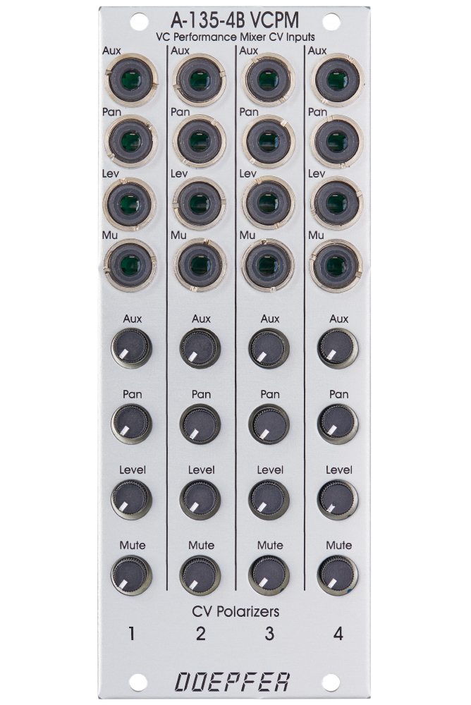
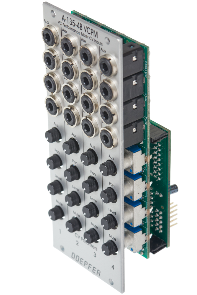
A-135-4B
This module is used to route the 16 external control voltage to the main module A-135-4A. These control voltages are available for each channel:
- Level (main loudness)
- Panorama
- Aux
- Mute
Each control voltage has an input socket and a polarizer control available (the polarizer function is described more detailed on the A-138c info page). That way it's possible to adjust the depth and polarity of the external control voltage which affects the parameter in question. If the same CV (e.g. LFO or ADSR) is used e.g. for two panorama control inputs the result may be the opposite if the polarizers are adjusted accordingly (i.e. one positive and the other negative). The external control voltage is added to the voltage that is generated by the manual control on the A-135-4A main module. The sum of both voltages is used to control the VCA in question and is displayed with the corresponding LED on the A-135-4A module. The picture on the left side below shows one channel of A-135-4A/B as block diagram.
The mute CV input works in principle in the same way as the level CV input but with reverse polarity and higher sensitivity (about factor -2). Typically the mute polarizer control is adjusted fully CW. Then a (gate) voltage of ~ +2.5V or more fully mutes the channel in question. If the mute function is not used the mute CV input can be used as a second CV input for level (with twice the sensitivity and inverted polarity compared to the normal level CV input).
A-135-4A and A-135-4B are connected internally via a 20 pin ribbon cable. The cable can be longer so that the CV input module A-135-4B needs not to be mounted next to the main module A-135-4A (e.g. to the row above or below).
Modules A-135-4A and A-135-4B are available only as a module combo because the single operation of each module does not make sense !